Every semester at GroupT there are “Engineering Experience” projects. Last semester I was part of the team who made the MuzaBot. But this time it was more serious. Designing our own PCB, selecting electronic components and reading lots and lots of datasheets gathering information we needed for our somewhat ambitious project.
The assignment was pretty simple: Design a competitive game with any electronics you like (but no LED matrices).
Pretty easy to come up with an idea, right? Wrong! A lot of people went with cliché stuff but, as always, we wanted something more. After some brainstorming we got our proposal approved, we were going to build a Motion Controlled Laser Maze Puzzle. In the end it boils down to this:
You are given a Wiimote with a custom accelerometer, and you wave around in the X-axis to spin a steppermotor which turns the angle of a mirror, likewise for the Z-axis. These mirrors deflect a laser beam, the purpose of the game is to guide the laser beam into a sensor which will defuse a bomb.
To make it somewhat more like a game, the bomb has a timer, so you have to be relatively quick or it’s game over. We’ve also added a moving wall which can obstruct a possible path of the laser beam, however, you can counter this by blowing into a mic.
There are three game difficulties:
Easy: wall doesn’t move
Normal: wall moves at certain intervals
Hard: wall moves at certain intervals and your controls get inversed at times.
That’s the idea for the game, the actual implementation was done with a PIC microprocessor (2553), software was written using C18 and the maze was milled and carved out of a wooden block.
The Wiimote controller
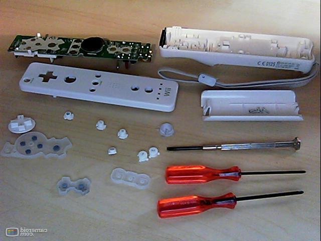
We opted to use a Wiimote because many people recognize it as a motion sensing controller. As we had no interest to use its bluetooth capabilities so we threw out most of the electronics and replaced the connectivity with a good old RJ-45 jack and an ethernet cable.
We ordered a Wiimote at DealExtreme which costed only $12 and started to take it apart.
The PCBs
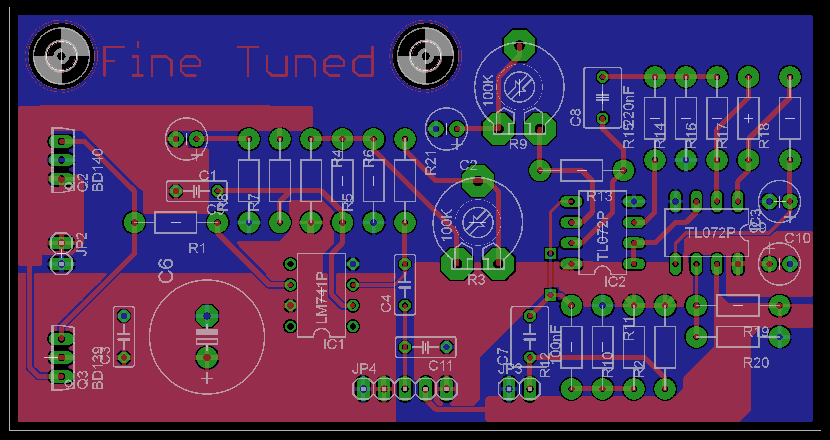
Not much to say here, we had to use Eagle to design the boards. Most schematics were pre-made for us (e.g. the mic pre-amp) so the most time went into making the actual pcb design. Even after countless of hours it’s probably below average quality but then again we haven’t had classes yet on how to create one.
These are the designs we came up with after several hours of trying different layouts. Both PCBs will be connected with a header to form one board, we had to split them up for money reasons as they’re ordered at some factory.
Software
Using MPLab to compile our code, sure, but don’t ask me to code in their IDE. For someone who’s used to Visual Studio this is a huge leap backwards. Luckily MPLab supports external editors which I set to PSPad which at least supports tabs.
As for the programming, luckily I had a C class this semester as well that has thought me a bit about coding in a procedural language (Visual Basic 6 has been way too long ago) rather than C# or Java. We spent some time structuring the code in several header and c files. The code will be posted in the next update.
Progress
That’s what we’ve got so far, after the Easter Holidays we get our PCB and components. We then have two to three weeks to get everything working, which shouldn’t be too much of a problem.


