Apr 12

Motion Controlled Maze Puzzle

Every semester at GroupT there are “Engineering Experience” projects. Last semester I was part of the team who made the MuzaBot. But this time it was more serious. Designing our own PCB, selecting electronic components and reading lots and lots of datasheets gathering information we needed for our somewhat ambitious project.

The assignment was pretty simple: Design a competitive game with any electronics you like (but no LED matrices).

Pretty easy to come up with an idea, right? Wrong! A lot of people went with cliché stuff but, as always, we wanted something more. After some  brainstorming we got our proposal approved, we were going to build a Motion Controlled Laser Maze Puzzle. In the end it boils down to this:
You are given a Wiimote with a custom accelerometer,  and you wave around in the X-axis to spin a steppermotor which turns the angle of a mirror, likewise for the Z-axis. These mirrors deflect a laser beam, the purpose of the game is to guide the laser beam into a sensor which will defuse a bomb.
To make it somewhat more like a game, the bomb has a timer, so you have to be relatively quick or it’s game over. We’ve also added a moving wall which can obstruct a possible path of the laser beam, however, you can counter this by blowing into a mic.

There are three game difficulties:
Easy: wall doesn’t move
Normal: wall moves at certain intervals
Hard: wall moves at certain intervals and your controls get inversed at times.

That’s the idea for the game, the actual implementation was done with a PIC microprocessor (2553), software was written using C18 and the maze was milled and carved out of a wooden block.

The Wiimote controller

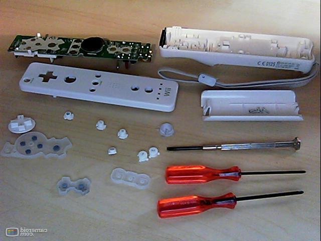
Wiimote disassembled

We opted to use a Wiimote because many people recognize it as a motion sensing controller. As we had no interest to use its bluetooth capabilities so we threw out most of the electronics and replaced the connectivity with a good old RJ-45 jack and an ethernet cable.

We ordered a Wiimote at DealExtreme which costed only $12 and started to take it apart.

The PCBs

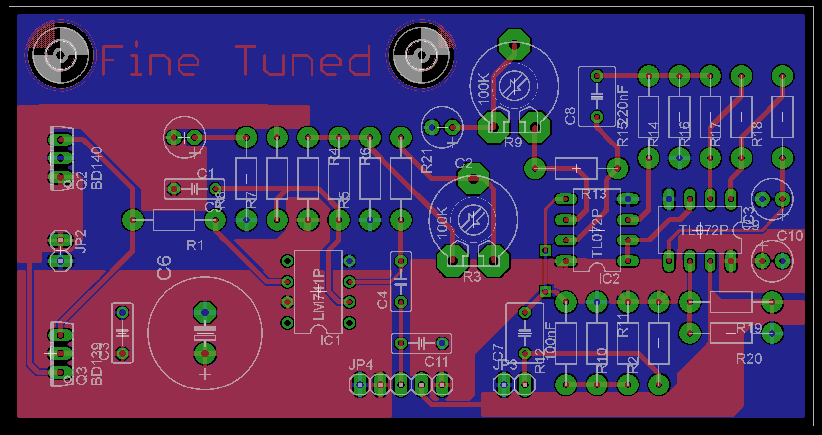
Not much to say here, we had to use Eagle to design the  boards. Most schematics were pre-made for us (e.g. the mic pre-amp) so the most time went into making the actual pcb design. Even after countless of hours it’s probably below average quality but then again we haven’t had classes yet on how to create one.

"Main" pcb
“Main” pcb

Mic pre-amp
Mic pre-amp

These are the designs we came up with after several hours of trying different layouts. Both PCBs will be connected with a header to form one board, we had to split them up for money reasons as they’re ordered at some factory.


Software

Using MPLab to compile our code, sure, but don’t ask me to code in their IDE. For someone who’s used to Visual Studio this is a huge leap backwards. Luckily MPLab supports external editors which I set to PSPad which at least supports tabs.

As for the programming, luckily I had a C class this semester as well that has thought me a bit about coding in a procedural language (Visual Basic 6 has been way too long ago) rather than C# or Java. We spent some time structuring the code in several header and c files. The code will be posted in the next update.

Progress

That’s what we’ve got so far, after the Easter Holidays we get our PCB and components. We then have two to three weeks to get everything working, which shouldn’t be too much of a problem.
Jan 19

De internationale community op Groep T

Dit jaar volg ik het vak “Signalen en Systemen” in het engels, “Signals & Systems”. Het gerucht doet de ronde dat het engelstalige programma gemakkelijker zou zijn dan het nederlandstalige. Da’s niet de reden waarom ik gedaan heb, maar bon, ik snap ook wel waarom er zoiets gezegd wordt.

Eerst en vooral *cultuurshock*.. In de hoorcolleges ligt een vierde van de Chinese medemens letterlijk te slapen! Bij een les lag zelfs de eerste rij, onder de neus van de docent, face down op hun bank. Een ander voorbeeld, een gsm rinkelt, de persoon neemt ‘m doodgewoon op, stapt buiten, doet z’n praatje en komt dan zonder enige schaamte de les terug binnen.
Wat mij hier vooral interessant leek is vertellen dat het hoorcollege gegeven wordt door een van de meest gerespecteerde docenten van GroepT. Die (het klinkt misschien slijmerig maar het is zo) gezag uitstraalt en verdomd goed les kan geven. Ik herinner mij dat er bijna wekelijks mensen werden buitengegooid bij Lineaire Algebra in het eerste jaar (NL programma) omwille van het storen van de les. Ze moesten eens weten..
Onze immer sympathieke Guido had het er wel al eens over tijdens z’n lessen management. De Chinezen hebben een totale andere mentaliteit. Ik wist dus wat ik zou kunnen verwachten maar dit gaat toch m’n petje te boven.

Het vak op zich is niet heel moeilijk, zodra je door hebt hoe de mechanische en elektronische applicatie oefeningen in elkaar zitten. Wat mij ergerde waren de ontelbare typ- en grammaticafouten in de cursus, alsook complete zinnen die nog in het nederlands stonden. Van een prof die de “Beste cursus” award gewonnen heeft een tweetal revues geleden verwacht je toch niet dat je zo’n spellingspuinhoop voorgeschoteld krijgt.
Net zoals maandag op het examen, er stonden misschien in totaal zes zinnen op de twee bladen waarbij 2 zinnen nog in het nederlands stonden en in een andere zin kilohertz verkeerd getypt was. Vreemd? Vind ik ook ja..

Om af te sluiten nog een interessant weetje. Het studentenforum heeft vanaf dit semester ook een engelse afdeling, de admins van het forum wilden hiermee de groeiende internationale community tegemoet komen. Merkwaardig is dat er nog geen enkel van hen iets op het forum gepost heeft terwijl er, zeker in de examenperiode, een zondvloed aan nederlandstalige posts bijkomt.

Dec 20

Maestro MuzaBot

Every year at GroupT there are one or two so called Engineering Experience projects. These projects usually involve a team consisting of around five people from the same year. This semester it was time for ‘Engineering Experience III’.

I started off mailing people even before the start of the semester because I wanted a good, functional team to work with. My dreamteam was a group of only EA (electronics) students, but it was not possible partly because I didn’t know enough people who are going to do EA starting next semester besides a couple of friends.
After a few requests and another handful of e-mails the composition of our team was finalized. Diversity  all around with two biochemical, one electromechanical and two electr(on)ical engineering students.

The objective of this project was to create a machine or robot that could be controlled by a computer using LabVIEW, Computer Based Control. Joy for the EA folks, a little less happiness at the other quadrants of the GroupT spiral. Nonetheless, no one has died from this course yet so there we were, trying to come up with a cool and realistic idea.

After an hour of brainstorming or so we had a couple ideas written down on the blackboard. Some were too hard to even consider them, others were too silly or too easy. Being a musical person myself I proposed a robot that could play some instrument, just like The Trons. Eventually everyone agreed and we quickly decided to use a metallophone  and some homemade drumming construction.

After over hundred hours (per person) of working on the software, construction and electronic circuits the result is pretty satisfactory. It could’ve been a better had we not neglected deadlines a couple of times (not gonna happen again, ever!) as we had to rush some things in the end to make it ready for the presentation.

The construction of the modules consist of Fischertechnik, LEGO and LEGO Technic blocks. Since those don’t always fit flush together we had to glue some things to make it work. The big parts are

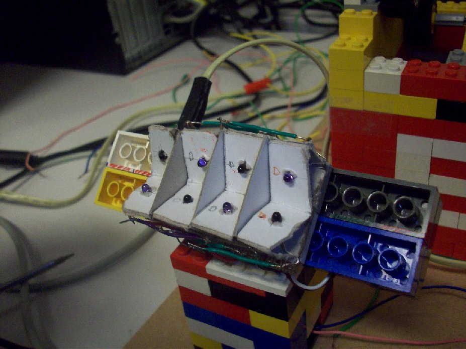
The Read Module

Read Construction

This part of the robot can read homemade music sheets which it translates to numeric values so LabVIEW knows how to handle it. This is achieved by using a set of IR-LEDs and IR-receivers (photo-transistors) . You feed the construction (not shown) a music sheet, it’ll detect it and start pulling it in. Once the sheet has gone through the reading part the motor automatically stops.

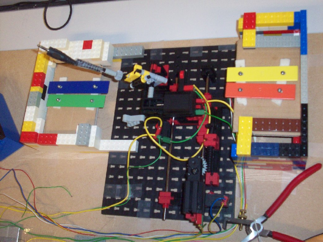
The Metallophone Construction

Metallophone


Next up is one of the two modules who take care of reproducing the music. This part contains 2 motors, four musical tones (C, D, E and F) and a couple of switches. Based on what is in the arrays the hammer will first move on the x-axis to the correct position and then move in an arc-like motion to ‘slam’ on the metallic plates. A bonus thing is, both this and the drum module are ‘in sync’ as they will hit their respective target at the same time.

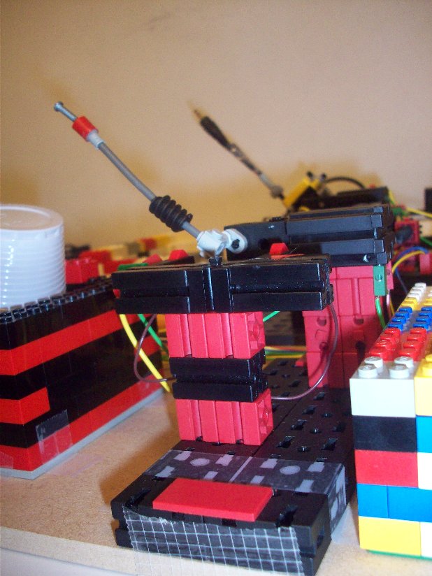
The Drum Module

Drum

The  drum can either hit a metal can or a plastic cup. This is the simplest construction of the robot as it only uses one motor and two switches put in parallel. As mentioned before, the hitting takes place as soon as the x-axis of the metallophone signals it’s ready to start the “hit” sequence.

The PCB and DAQ

PCB


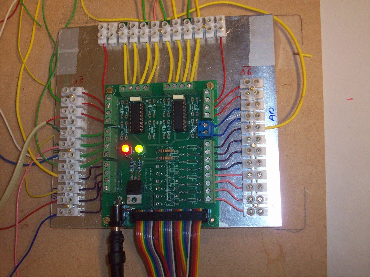
The missing link between the modules and LabVIEW on our computer is the actual PCB which every electronic component is connected with. This specially designed for this course circuit board contains some basic things such as 9V and 5V voltage sources as well as other in and out gates. Another interesting component is the H-bridge so we could easily make the motors run in both directions.

Aside from this PCB, we also had a National instruments DAQ card, the 6008-USB. This DAQ-card was hooked up with a computer which runs LabVIEW. It’s relatively cheap but it’s got more features than we could’ve asked for.

GUI

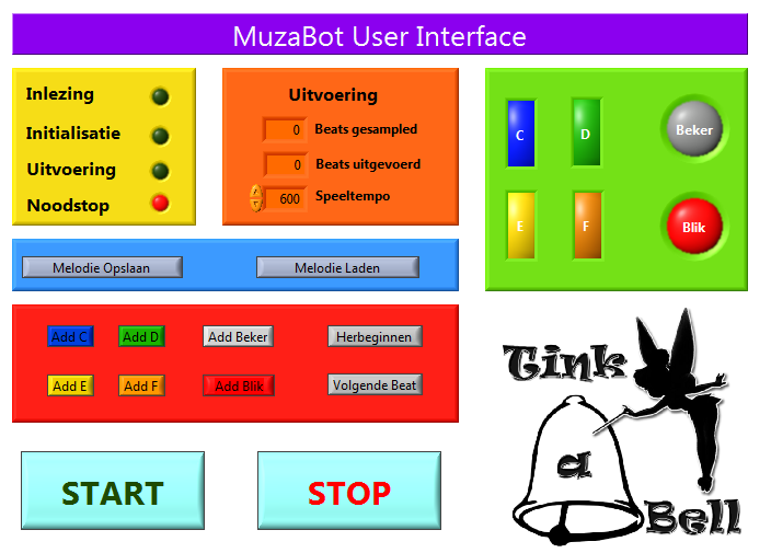
Actually using and controlling the robot can be done through a GUI I made. Here you can see what is going on (yellow part), how many beats are ready to be played and how many have already been played (orange) and the virtual representation of what is being played (green).
The blue and red parts are the areas where you can either save/load music or enter your own tunes. This makes a total of three ways to add music information into the robot.

This project was a lot of fun in my opinion, and I’ve learnt a lot by designing the program in LabVIEW and helping with the construction of the different modules. Last but not least, feel free to check out the following video of the machine in action (sorry for the crappy audio/video quality!)